The Pancake printer
Together with Daniel we created a pancake printer for our exam in Design and process, electricity at HTX.
We had to create a sufficiently advanced project. It had to include at least a microcontroller and a self developed PCB board. During the exam it would be judged on how advanced / how many features the project had and how well documented everything is. How the project was constructed physically would not count.
This project was a challenge in electronic design, microcontroller programming and construction shortcuts.
Production and design
After having spend way too much time trying to create the 2D printer in bent sheet metal, with no success at all, we had to find a printer design which we could create in a hurry. That was when we stumbled upon the CoreXY printer design. With this design we could make a baseplate out of stiff mdf wood. We also didn’t have to worry about weight on the printhead (Since the x/y motors are kept on the side), therefore the whole construction didn’t have to be as sturdy.
The design was pretty simple to build since we could order the rods online and print the 3D mounts at the school. It was also surprisingly accurate since all of the precision was in the rods and the 3D printed parts.
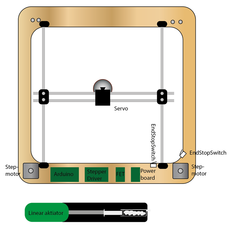
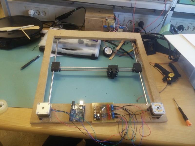
The planned design vs the build printer.


PCB Design and print
While waiting for the printer rods and bearings from china, we started working on the PCB.
Our design has two stepper motors. To drive these, we wanted to use the L293D Quadruple Half-H Drivers. They are pretty powerful and can be easily controlled from the arduino using a pre-made library. We needed to make a circuit board which would provide control signals and 5V power as well as 12V power for the stepper motors. We also wanted to include a semi-large capacitor to help smooth out current spikes. And lastly we added LED’s to show in which direction the power was flowing on the different motor windings. This would help us debug any problems with the PCB.
We started by creating the schematic in Eagle. Next we made our first iteration of the board. Here the design was plotted on a PCB-board using the different component footprints, which matched what we had in stock. The first iteration was pretty awful, but it had all the components connected. The next iteration was much better. It was physically a lot smaller and it included larger tracks for the high current connections. It also included some copper heatsinking for the H-drivers. The final design included more improvements such as larger solder pads and mounting holes.
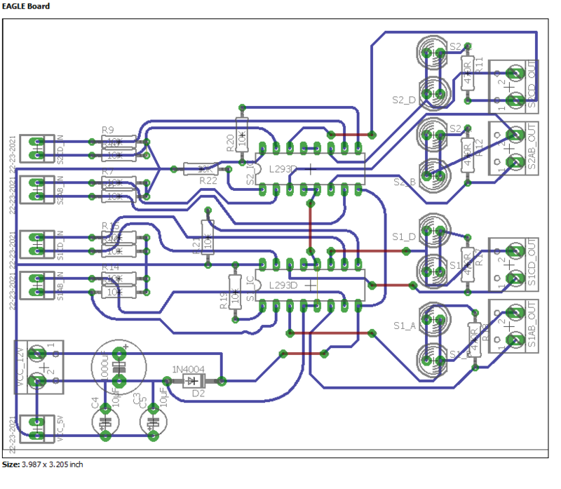
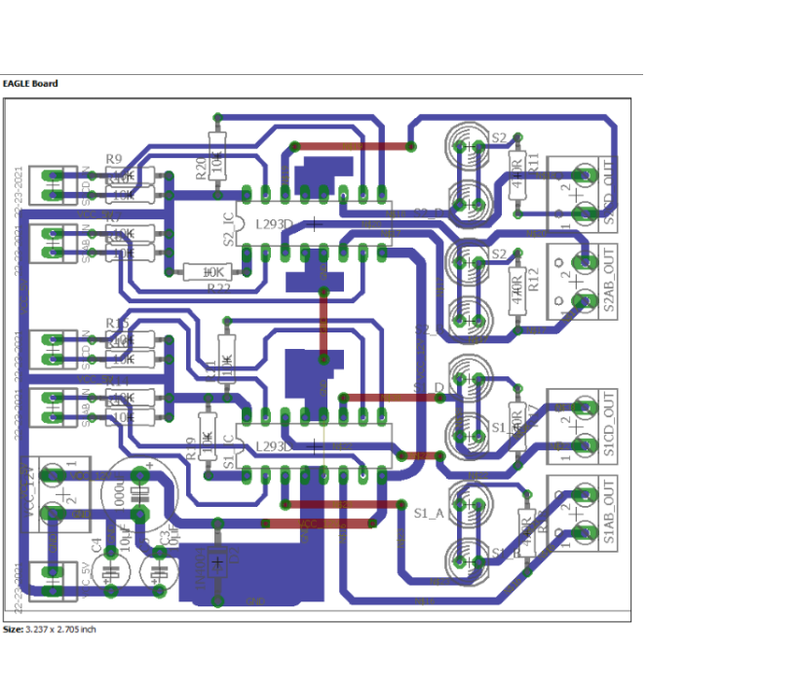
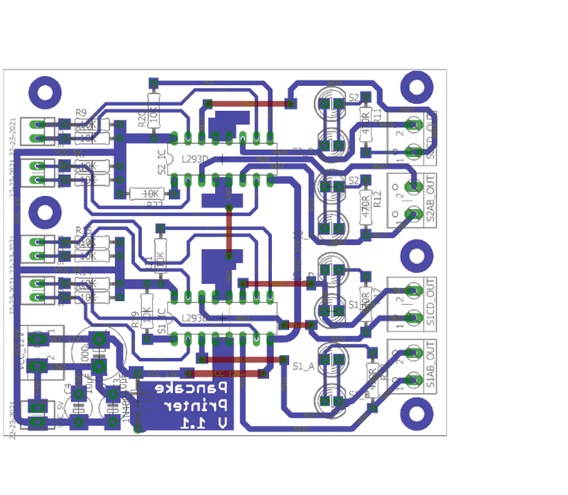
The different iterations of our PCB.


The next step was to print out the circuit board. This was done in the old fashioned way. First we had to expose a blank copper PCB to our printed circuit design. Next we had to dissolve the extra cobber in an acid bath. Then we had to drill out all of the small holes. Lastly it was time for soldering on the different components and praying for it to work.
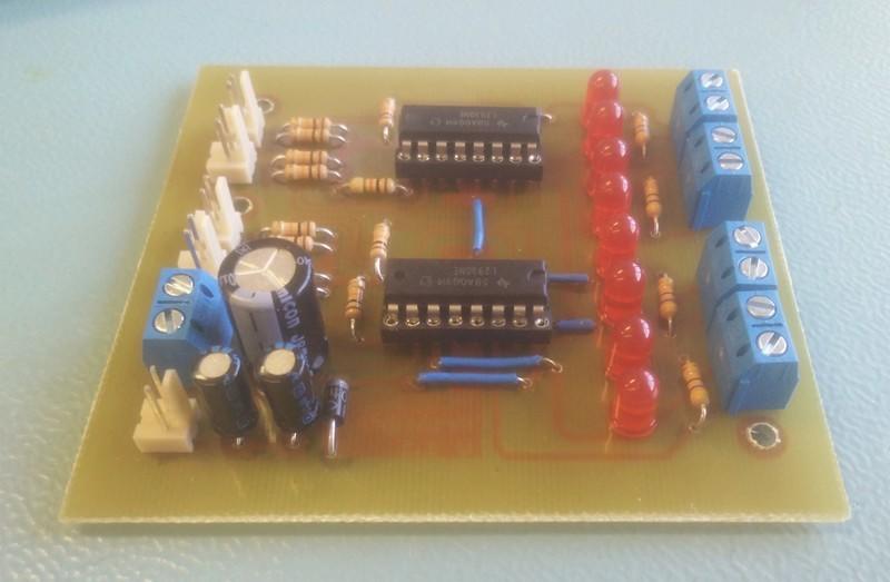

The printed and soldered circuit boards.


The first thing we did after the print finished, was to test our board. We had of course already tested the schematic on a breadboard, so it should work if the PCB was designed and printed right. We did a simple test with two stepper motors running in sync.
Physical construction
As said earlier, the physical appearance of the project didn’t effect our grades, so we never actually mounted the parts properly. There is nothing more permanent than temporary tape mountings.
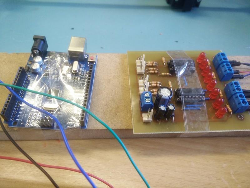
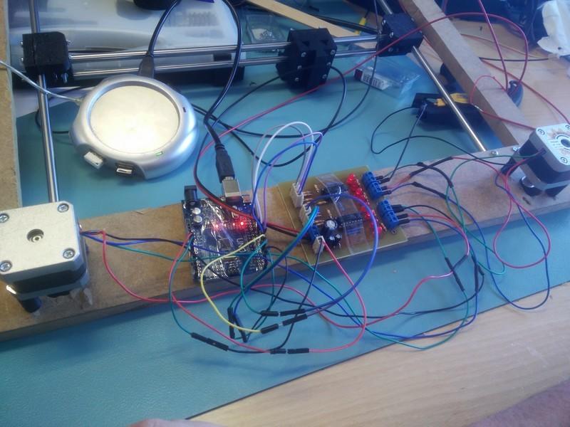
No time wasted on mouting.


We also had to figure out how to dispense the pancake dough on the heated pan. We researched different pump systems such as a peristaltic pump. The problem was, we were low on time and the flow rate would be really slow (might not work at all with pancake dough). We couldn’t use a regular water pump, since it would likely cluck up and would be difficult to clean. In the end we found an easy solution by using an electronic caulking gun and a large syringe.
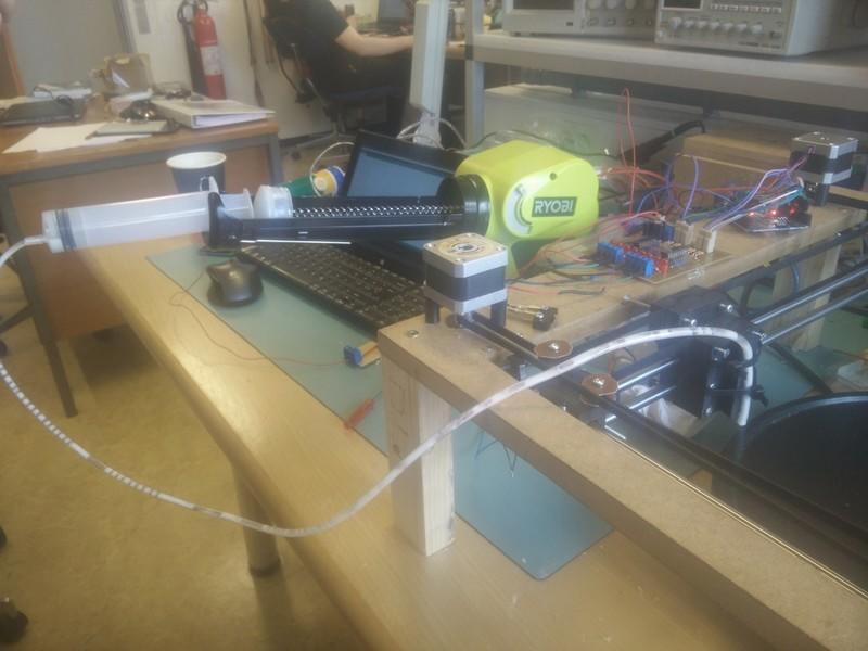
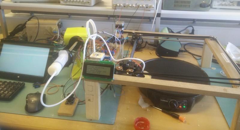
The final physical design of the printer.


The printhead had a tendency to drip, so we later installed a servo with the bottom of a soda can glued on it, which could catch drops of dough when not dispensing.
Using the Arduino and a LCD we created different control modes for the printer:
- Build-in test shapes
- Manual control using joystick
- Serial control (to enable use with applications on the computer)
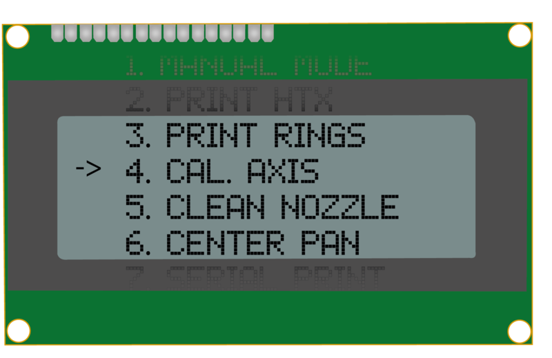
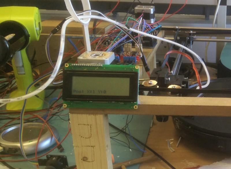
The LCD displays the printer status and is also used to control the printer.


Test prints
The last images here show the build-in test prints.
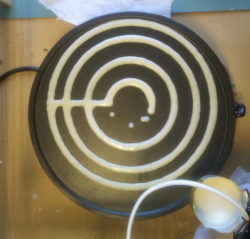
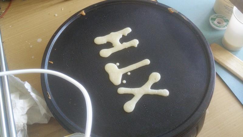
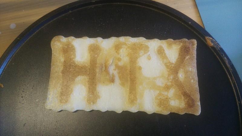
Build in test prints.


Personal takeway
This project was a challenge in electronic design, microcontroller programming and constructional shortcuts.
I got to practice my skills in circuit board design and routing using Eagle. I gained experience making all of the pieces work together using different voltages and control methods while creating friendly user interfaces.
- Team member:
- Daniel Dalgaard Andersen
View my other projects.
Education Hardware